
Mass Spectrometry
Isotopes
The radioactive decay of a parent isotope to a daughter isotope changes the isotopic composition of both the parent and daughter elements over time. The rate of such decay is measured in terms of the "half-life" - the time it takes for 50% of a given quantity of a radioactive isotope to decay to its daughter product.
Some half-lives can be measured in nano-seconds, others in billions of years. The ones that geologists are interested in are usually on the longer side, and include:
- the beta-decay of 87Rb to 87Sr, 176Lu to 176Hf and 187Re to 187Os
- the alpha-decay of 147Sm to 143Nd
- the multiple decay series of uranium and thorium to lead
These schemes are of interest for two main reasons:
- they allow us to date the age of rocks
- they allow us to examine and identify heterogeneous parts of the earth such as components within the mantle, or the history of seawater composition, etc.
We also use non-conventional stable isotopes, such as Li, K, B, Mg, Ca, Fe, Cr, Zn, Cu, and Mo, to look at physical and/or chemical processes which lead to isotopic fractionation in nature.
Isotope Analysis
To measure isotopes, we need to take our specimen (rock, water, organic material) and isolate the elements under investigation. This is done by dissolving the sample in acid and using ion-exchange column chromatography to separate out our sample into its component elements.
To get very high-precision data, we measure isotopic ratios rather than absolute isotopic quantities. We normally look at ratios of the parent or daughter isotope compared to other isotopes of the same element which are not involved in any decay scheme. And to carry out these measurements, to an extremely high degree of precision, we use a mass spectrometer.
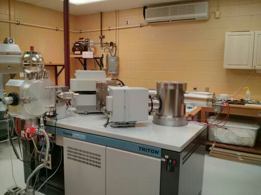
ThermoFinnigan Triton TIMS
Once we have our element separated, we take it into solution and dry it down onto a filament ribbon made of tantalum (for strontium) or rhenium (all other elements). Each time we run a batch of samples we also load at least one international standard which is the first filament to be run, to check that the machine is operating correctly.
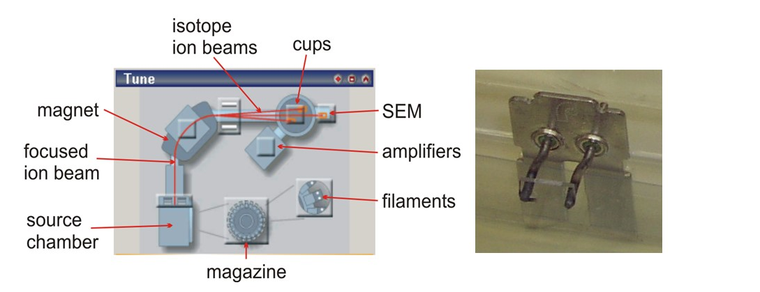
Magazine
Up to 21 filaments can be loaded onto the magazine for each run. The magazine is loaded into the machine's source chamber and pumped down for at least 90 mins; more commonly overnight. We need to obtain a vacuum of less than 3x10⁻⁷mbar in the source chamber before proceeding further.
To run a sample, we pass a current through the filament to heat it up to the ionization temperature of the element in question - normally somewhere between 900 and 1900oC. There is a pyrometer on the front of the source chamber which measures the temperature of the filament under analysis.
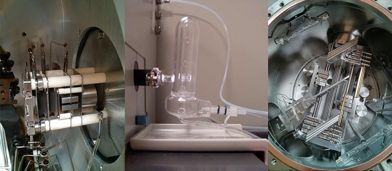
Focus
Once the filament is heated up, and the sample is ionizing, ions will be emitted from the filament. These need to be focused into a beam which is then fired down the flight tube towards the magnet. To focus and accelerate the beam, we have a series of high-voltage electrostatic extraction and condenser source plates just next to the filament being analysed which can be adjusted to produce an optimum signal.
Magnet
The focused beam of ions is fired, under high vacuum, down the flight tube. This has a bend in it, with a powerful magnet wrapped around the "bend". The magnet deflects and bends the beam of ions, separating it into its constituent isotopes which then continue down the flight tube, each in their own separate beam. Higher masses bend less than lower masses - hence the separation of the isotopes The deflection power of the magnet is adjusted for each element.
Cups
The individual isotope beams are collected in cups at the end of the flight tube. There are 9 cups on this machine - one fixed in the middle (the centre cup) - and 4 adjustable cups on each side. The cups are adjusted to optimal positions to collect the isotopes of the element being analysed. We also have a single secondary electron multiplier (SEM) for samples with very tiny signals - often used for U-Pb dating.
Amplifiers
Every positive ion which hits a cup is neutralised by an electron from the cup's amplifier. This creates an electric current within the amplifier. A typical signal corresponds to approx 0.1 billion ions per second! The amplified signals are digitized and then sent to the computer for you to work with. The amplifiers are calibrated once a day.
Software
The TRITON is software-driven. Initial set-up each day includes setting the magnet, cups, and focus parameters for the element being analysed and doing an amplifier calibration. Once each sample is warmed up, focused and ready to run, a method is chosen to control the way each run is carried out. The standard is run, to check all is well, followed by the samples. It is important that the samples are run in as identical way as possible to the standard. The data file from each run is given a unique name and saved on the computer.
ThermoFinnigan Neptune MC-ICP-MS
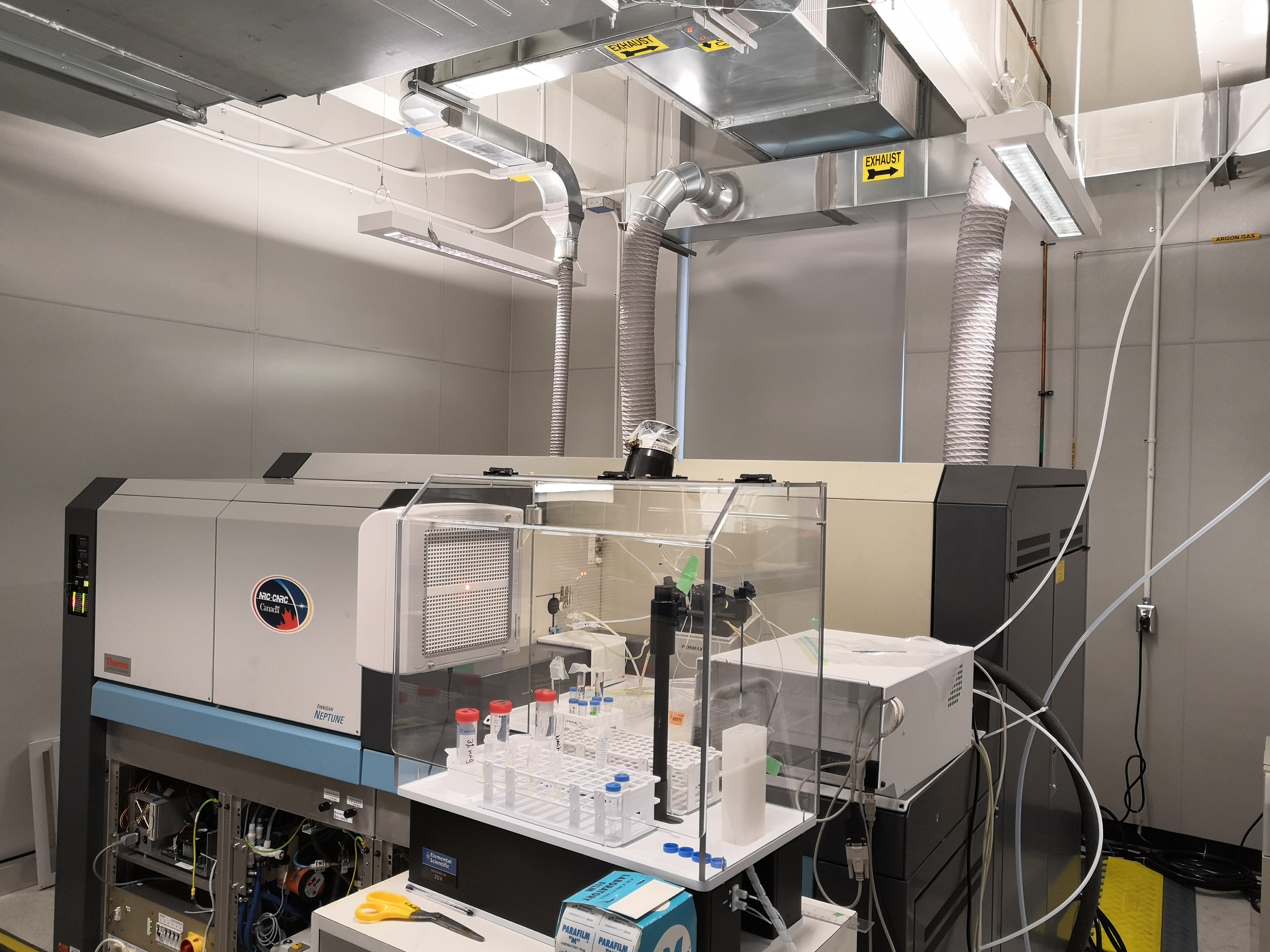
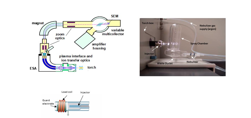
An aliquot of sample is taken into certain volume of 2% HNO3 to make a wanted concentration of sample solution, which is then picked up by the autosampler and aspirated through a nebulizer at a flow rate of 50 to 100 microliters/minute. At the tip of nebulizer (connected to an argon gas flow at a rate of around 1 liter/minute, called sample/carrier gas), a stream of sample aerosol is formed because of the Venturi effect. The droplets in the aerosol are further refined in the spray chamber-the large droplets are condensed on the wall and drained to the waste line, while the fine droplets (less than 10 microliter in size) are carried to the torch through the injector at the centre of the torch assemblage.
A desolvating nebulizer (such as Teledyne Cetac Aridus and ESI Apex Omega) can be used to produce dry sample aerosol using an exterior argon flow to sweep off the solvent vapors when the nebulized sample aerosol passes through a heated fluoropolymer tubular membrane. The desolvating nebulizers can substantially improve the ICP ionization efficiency.
An in-situ spatial-resolved isotope analysis can be realized through coupling a laser ablation system with the Neptune MC-ICPMS, examples such as in-situ Hf isotope analysis for a single zircon grain, Sr isotope analysis for otoliths. During the laser ablation, the ablated sample particles are directly delivered to the plasma. Laser ablation system is not currently available in the IGGRC facility.
Torch
Neptune’s torch assemblage is constructed with three concentric quartz glass tubes coiled with a water-cooled hollow copper wire, called load coil. The torch’s intermediate tube is connected to a low flow rate (0.8-1.0 liter/minute) argon gas, called auxiliary/plasma gas) in which the plasma is induced; its outmost tube is connected to a high flow rate (16 liter/minute) argon gas, called cooling gas that shapes the plasma and prevents the torch glass from melting. The inner tube is the sample injector through which the sample stream is injected to the torch; injector is adapted to a spray chamber or a sample transfer line from a desolvating nebulizer or a laser ablation system.
The argon ICP (with a temperature of > 8000 K) is formed and sustained when a RF current-powered load coil inductively couples auxiliary argon gas into a 27 MHz electromagnetic field. In order to achieve a robust ICP condition, a minimum 60 minutes warming-up period is needed.
The fine sample droplets or particles (in the case of laser ablation) are carried through the injector (by the argon gas flow) into the ICP torch, where the analyte droplets are desolvated, atomized and ionized at an extremely hot gaseous environment (hotter than surface of the sun).
To optimize the instrument performance, the sample and auxiliary gas flow rates, the plasma torch’s adjustable positions of X (left and right), Y (up and down) and Z (towards and away the sample cone), must be tuned carefully.
ICP Interface
The water-cooled ICP interface bridges the plasma and the ESA where the ion swarm coming out of the plasma is sequentially pulled through the orifices of sample and skimmer cones because of the pressure difference between the plasma (open to atmosphere) and the interface (under a vacuum level of 1 to 3 millibars). The condition of the sampler and skimmer cones is one of the important factors affecting the performance of the instrument.
Ion Transfer Optics
The ion transfer optics is immediately next to the interface to initially accelerate and focus the ion beam onto the entrance slit before it enters the ESA. It is more or less functions as the ion lens stack does in the Triton TIMS’ source, but it requires much less tuning once it’s settled down in line with a particular ICP inlet setting.
ESA
ESA combined with a magnet sector analyzer, configures the Neptune MC-ICPMS as a double-focusing mass spectrometer. ESA works as an energy filter to eliminate a wide energy distribution of the ion beams before they head to the magnetic analyzer. It is made of two curved and paralleled metal plates (left and right) and two additional Matsuda plates (top and bottom). ESA is supplied with such a high voltage that it only allows the ion beams with a specific range of kinetic energy to pass through the ESA tube.
Magnet, Cups, Amplifiers and software
The ion beams emerging from the ESA, are finally accelerated at a10KV lens, and through the intermediate slit enter the magnetic sector analyzer where they are deflected and focused onto their designated Faraday cups on the basis of their mass/charge ratios. Please refer to the above descriptions of Finnigan Triton’s Magnet, Cups, Amplifiers and Software to understand how the ion beams are received by the cups and converted to the readable signals by the amplifiers, and subsequently recorded and processed by the software.